Views: 161 Author: Site Editor Publish Time: 2021-04-13 Origin: Site
How to install the splitter distribution box is the important information we need to know. This article includes the following:
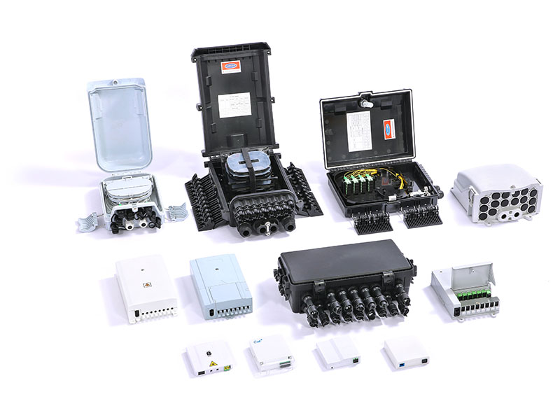
3. Box installation and fixed splitter distribution box
5. Ground the installation system

Figure 2-1 Expansion screw

Figure 2-2 Wire tie
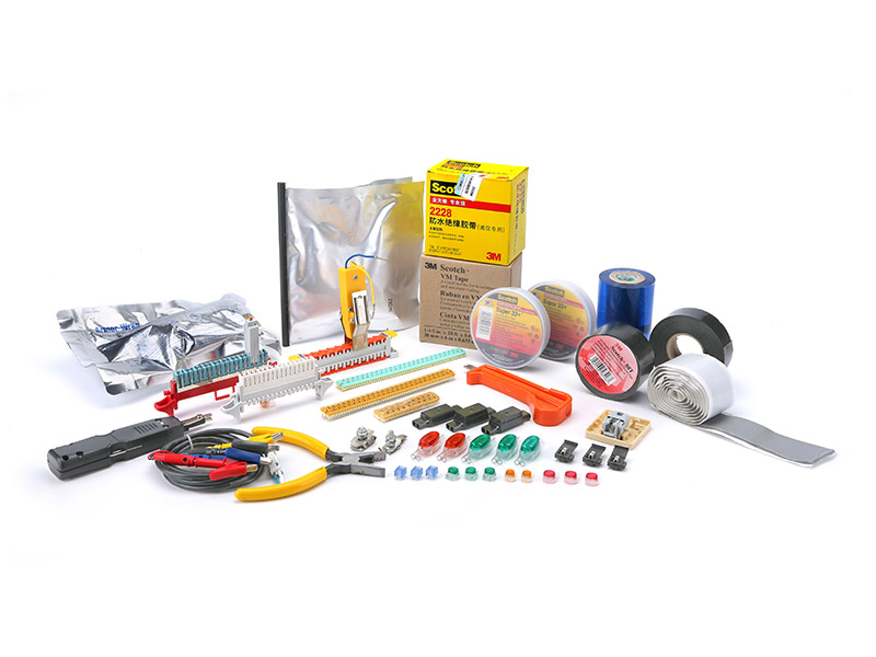
When installing and fixing the optical fiber distribution frame, an impact drill, hand hammer, and socket wrench are used, as shown in Figure 2-3. When stripping the optical cable, several types of wire strippers are used, as shown in Figures 2-4, 2-5, 2-6, etc.

Figure 2-3 Bare fiber stripping pliers

Figure 2-4 Stripping pliers for opening the outer sheath

Figure 2-5 Bare fiber stripping pliers
In addition to the above-mentioned tools (including wrenches and screwdrivers), professional single-core fusion splicers or ribbon cable fusion splicers are also used.
1) Drill holes at the selected position according to the installation dimensions (as shown in Figures 2-7 and 2-8).

Figure 2-6 Percussion drill drilling

Figure 2-7 Hammered expansion bolts
2) Put the ftth distribution box to the corresponding position, and tighten the four screws with your hand and the socket wrench (Figure 2-9)).

Figure 2-8 Tighten the screws by hand

Figure 2-9 Tighten the screws with the hand wrench
Note: The installation of the GPX99-B optical fiber distribution box is slightly different. That is to say, wall-mounted installation and rod-mounted installation can be realized (as shown in Figure 2-10 and Figure 2-11).

Figure 2-10 Installation and fixing of the outdoor wall-mounted fiber distribution box

Figure 2-11 Installation and fixing of outdoor hanging rod optical distribution box
1) ODF application principle (Figure 2-12).

Figure 2-12 Outline of the application of optical cable and optical equipment interconnection

Figure 2-13 Front view of lower cable entry
2) The ODF box body enters the cable.
(1) The on-site cable entry of the GPX99-C series optical fiber distribution box is shown in Figure 2-13.
(2) For different optical cables, users can flexibly wrap tape as shown in Figure 2-14.
(3) Press the tape-wrapped fiber optic cable onto the cable inlet of the box as shown in Figure 2-15.
(4) Finally, use silicon rubber to paste the rubber strip in the groove of the cable opening and pressing part.

Figure 2-14 Wrapping tape

Figure 2-15 Press-fitting an optical cable
Note:
(1) The adhesive rubber strip must ensure the continuity of the upper and lower covers of the box to ensure the sealing of the splitter distribution box.
(2) The imported box of GPX99-B meets the IP66 standard, that is, anti-flame retardant and anti-pressure water. Users can follow the operation of the GPX99-C series to realize the up and down cable feeding of their box.
3) Stripping, fixing, and protection of optical cable
(1) Lead the optical cable into the fiber optic cable box from the upper or lower cable entry hole. Use the fiber optic cable fixing sleeve to tighten at the entrance. (Figure 2-16)

Figure 2-16 Stripped length of optical cable
(2) In the outdoor optical fiber distribution box, when stripping the non-ribbon optical cable, wrap the bare fiber in the protective sleeve at the position shown in the figure with insulating tape (Figure 2-17).

Figure 2-17 Stripping the optical cable

Figure 2-18 Binding and fixing the optical cable
(3) Next, thread the reinforcing core of the optical cable into the grounding copper bar. Then tie the armor layer with thread or thin iron wire to the position shown in Figure 2-18.
(4) Tighten the reinforcing core, as shown in Figure 2-19.
Note: For indoor fiber distribution boxes, stripping and fixing are slightly different, as shown in Figures 2-20 and 2-21.
Difference:
(1) Be sure to fix the armor layer with a throat button
(2) No need to use bare fiber stripping protection device
(3) No need to use bare fiber protection sleeve

Figure 2-19 Fixed reinforcement core

Figure 2-20 Throat buckle fixed armor layer

Figure 2-21 Fixed reinforcement core
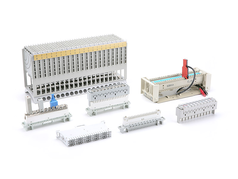
4) Installation of GPX99-B adapter and pigtail
(1) Pull out an optical fiber connection module from the rotating plug-in box and place it on the workbench. Remove the upper and lower cover plates, and install 12 adapters (FC, SC, or ST with flange) into 12 single-core pigtail heads. Then align the installation groove and press it in from top to bottom (Figure 2-22).

Figure 2-22 Placing a single-head pigtail
Note: The character side of the adapter must face up, as shown in the enlarged view of Figure 2-22.
(2) Wind the redundant pigtail on the fiber surface of the module and the winding area of the pigtail 1-2 times. Tie the 12 pigtails at the position shown in the figure with a cable tie (Figure 2-23). Then, thread the pigtail to the front according to Figure 2-24.

Figure 2-23 Disk storage pigtail

Figure 2-24 Arranging pigtails
(3) Cover the welding cover (as shown in Figure 2-25). Store the 12 single-core pigtails with the sheath removed in the fusion splicing area on the front of the module, as shown in Figure 2-26. Close the upper cover.

Figure 2-25 Cover welding cover

Figure 2-26 Arrange the pigtails to be spliced
5) Installation of adapters and pigtails of GPX99-C series splitter distribution box
(1) GPX99-C series optical cable wall-mounted boxes all use small fusion splicing modules and install a six-position or eight-position adapter cardholder near the fusion splicing module (as shown in Figure 2-27).
(2) The user can flexibly route the cable to ensure that the radius of curvature is not less than 40mm (Figure 2-28). For specific fiber routing, please refer to (Figure 2-35).

Figure 2-27 Install the adapter on the card socket

Figure 2-28 Non-strip optical fiber cable routing
6) Fusion splicing of pigtail of GPX99-B fiber splitter distribution box
(1) Take out the splicing module and place it on the welding workbench. Uncover the front cover and release the pigtails stored in the splicing area (as shown in Figure 2-29).
(2) Fix the end of the bare fiber protection sleeve of the outer cable with a cable tie at the position shown in the figure (Figure 2-30). Lead the remaining suitable length into the welding table.
(3) As shown in Figures 2-31 and 2-32, use a stripping shear to strip 12 single-core optical cables and non-ribbon optical cables.

Figure 2-29 Stripping single-core optical cable

Figure 2-30 The fiber cores are exposed after stripping
(4) Clean the core with a solvent, and then cut the core, as shown in Figure 2-31. Finally, splice (as shown in Figure 2-32).

Figure 2-31 Cut the fiber core

Figure 2-32 Fusion spliced fiber core
(5) Push the welding protection sleeve so that the welding point is in the center. Then put it in as shown in Figure 2-33 for heat shrinking.

Figure 2-33 Melting and welding protection sleeve

Figure 2-34 Finishing the core after fusion splicing
(6) Put the spliced fiber core neatly into the splicing area (as shown in Figure 2-34).
7) Fusion splicing of pigtails of GPX99-C splitter distribution box
(1) As far as the splicing part is concerned, the indoor optical fiber distribution box uses splicing modules. The outdoor optical fiber distribution box uses the splicing module, and its welding operation is exactly the same as the optical cable stripping method.
(2) The disk storage process in the splice tray is shown in Figure 2-35. There are two parts, the outer disk storage, and the inner disk storage, and the directions are as shown by the arrow.

Figure 2-35 Pigtail storage in the splice tray
So far, in addition to grounding, the entire optical fiber distribution box has been installed and spliced.
1) Grounding of the indoor optical fiber distribution box (as shown in Figure 2-36)

Figure 2-36 Grounding the indoor optical fiber distribution box

Figure 2-37 Grounding the outdoor optical fiber distribution box
2) Ground the outdoor optical fiber distribution box (Figure 2-37)
The outdoor optical cable must be well grounded when it is stripped and fixed, as shown in Figure 2-38.

Figure 2-38 Grounding the outdoor optical cable during stripping and fixing